Here is an overview of some of the most common avionics network and data bus technologies, presenting key features required to support test applications and examining some off-the-shelf PXI test instruments that provide support for these key features
by Troy Troshynski, Avionics Interface Technologies
The MIL-STD-1553 protocol standard was first published in 1973 by the U.S. Department of Defense (DOD) and was originally used for the Lockheed Martin F-16 program. Currently, MIL-STD-1553 is ubiquitously used for a large number of military and civilian avionics applications world wide.
MIL-STD-1553 standard
It is even used on the International Space Station (ISS) and in ground based vetronics systems. It is estimated that about 30,000 aircraft are in operation using MIL-STD-1553. Today, MIL-STD-1553 continues to be designed in to new programs such as the Airbus A350, F-35, and several UAV programs. MIL-STD-1553 provides a shared data bus (redundant) and supports up to 31 terminal devices (Remote Terminals) and a single controller (Bus Controller). An unlimited number of monitoring devices (Bus Monitors) are allowed on the bus. All MIL-STD-1553 communications or data transfers are initiated by the Bus Controller which can issue 3 types of commands:
- bus controller to RT transfer command
- remote terminal to bus controller transfer command
- remote terminal to remote terminal transfer command.
MIL-STD-1553 utilizes a redundant bus architecture. The Bus Controller tries commands to the Remote Terminals on one of the redundant buses, if no response is received the Bus Controller does a retry of the command on the other redundant bus. Most aircraft systems utilizing MIL-STD-1553, utilize several buses are within different subsystems. For example, an F-16 uses at least 5 independent MIL-STD-1553 buses. When considering a test instrumentation system for this type of application, several MIL-STD-1553 bus interfaces are typically needed. As a result, it is desirable to have a single instrument (PXI I/O board) capable of providing multiple MIL-STD-1553 bus interfaces. Because the MIL-STD-1553 bus speed is relatively slow (1 Mbit/sec) many redundant bus interfaces are possible in a single PXI slot.
![]()
Simulating nodes
For single subsystem, or individual device, test applications, (e.g. one MIL-STD-1553 bus interface), it is often a requirement to simulate multiple bus nodes. For example, the test instrumentation may have to simulate the Bus Controller and several Remote Terminals that the UUT communicates with in a real system.
As a result, a MIL-STD-1553 test instrument must also have the ability to simulate one or many of the possible MIL-STD-1553 bus components in parallel for each of the available bus interfaces. In addition to supporting multiple bus interfaces and the simulation of multiple bus components, MILSTD- 1553 test instruments must also provide the ability to both detect and inject protocol errors. Therefore, MIL-STD-1553 test instruments cannot use a dedicated commercially available MILSTD- 1553 chip-set solution which is restricted to only legal protocol operations.
A specific test instrumentation protocol engine must be supported, typically within an FPGA to allow customizations. MIL-STD-1760 is a weapons interface specification which uses MIL-STD-1553 for signaling between an aircraft and a munition. In addition to MIL-STD-1553, MIL-STD-1760 also uses high voltage discrete I/O signaling. In order to support MIL-STD-1760 test applications, a robust MIL-STD-1553 test instrument must also provide 28V DIO lines. Because many MIL-STD-1553 avionics applications also require synchronization with external events and timing interfaces such as IRIG-B, the ability to synchronize the on-board clock to IRIG-B is an important feature of any test instrument.
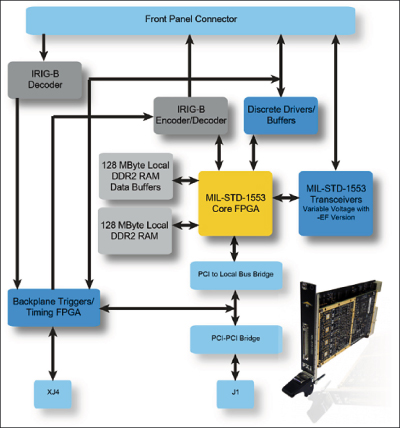
The AIT MIL-STD-1553 PXI Test and Simulation module provides an example of a test instrument providing the key features and functions discussed.
This PXI instrument provides the ability to synchronize with other common test instrumentation via the use of PXI Triggers, PXI 10MHz Clock and PXI STAR trigger. This test instrument also provides an IRIG-B Encoder and Decoder which allows the module to either be a time master or slave in support of clock synchronization with external IRIG-B enabled devices. Ten high voltage (up to 30V) DIO lines are also provided in support of MILSTD- 1760 applications. The MIL-STD-1553 protocol engine IP was developed entirely in-house by AIT specifically to support test and simulation applications.
The protocol engine IP is hosted in a core FPGA which also provides an embedded 200 MHz PowerPC to support custom high performance test application requirements. The instrument supports up to four (4) dual redundant MIL-STD-1553 bus interfaces in a single 3U PXI slot and is capable of simultaneously simulating a Bus Controller, Bus Monitor and up to 31 Remote Terminals independently for each bus interface. Additionally, each bus interface is software reconfigurable to support direct, transformer, and emulated bus network connections to the MILSTD- 1553 bus or directly to the UUT without the requirement for and external bus network.
ARINC 429 protocol
ARINC 429 is most widely used in commercial aircraft such as the Boeing 737, 747, and 787 as well as the Airbus A330, 340, 350, and 380. The protocol was initially specified in 1977 and is a simple serial data link supports 100Kbit/sec, 25Kbit/sec, and 12.5Kbit/sec options. ARINC 429 data is transferred in 32-bit words. The data contained in each 32-bit word is identified by an 8-bit Label ID. Other optional data fields are provided to further identify the payload data. ARINC 429 uses odd parity (the last bit of a 32-bit bus word is a parity big).
However, some avionics applications have chosen even parity and in some cases the parity bit may be used as an additional bit for data. All ARINC 429 data links are unidirectional with one transmitter and one or more (multi-drop) receivers. A differential (2-wires) bipolar return-to-zero encoding scheme is used. Two main ARINC 429 test scenarios must be considered with respect to test instrumentation. One is the case of a single Line Replaceable Unit (LRU) being the Unit Under Test (UUT). In this case the UUT will typically have multiple ARINC 429 inputs and outputs.
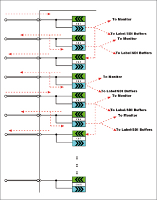
For this reason the ARINC 429 test instrument must have the ability to support a combination of several input and output ARINC 429 channels within a single PXI slot. An example of an optimal ARINC 429 test instrument, is the ability to support up to 32 ARINC 429 interfaces with each interface being individually programmable to act as either an output (Tx) or input (Rx) interface. Additionally, the test instrument should provide the ability for each ARINC 429 interface to be independently configured to support the 100Kbit/sec, 25Kbit/sec, and 12.5Kbit/sec bit rate options.
For point-to-point test scenarios the set equipment must support error injection and detection. The second common ARINC 429 test and simulation scenario is associated with system integration applications where several components of an avionics system may be present. In this scenario, the test instrument must provide the ability to pass ARINC 429 data through from an input channel to an output channel. While passing the ARINC 429 data through, the test instrument must be able to log the data and to inject errors and modify the payload content.
Robust simulation
 As with MIL-STD-1553, PXI provides an ideal solution for a robust ARINC 429 test and simulation instrument. For example, the AIT ARINC 429 PXI Test and Simulation module utilizes the PXI Trigger, 10MHz Clock, and STAR trigger mechanisms to provide a solution that allows the synchronization of ARINC 429 bus events with common test PXI instruments such as function generators, digital oscilloscopes, and timing and synchronization modules. AIT’s ARINC 429 PXI module provides up to 32 ARINC 429 channel interfaces.
For maximum flexibility, each of the 32 channels is independently programmable to operate as either an input or an output channel and all output channels provide an internal digital loop-back so that all output data can be logged and compared to responses received from a UUT at the input channels.
In order to support system integration and test applications, the module allows any input ARINC 429 channel to be associated to any output ARINC 429 channel to provide a data path through the module. As data passes through the module, the application software can configure the test instrument to modify, add, and remove data words. Additionally, errors can be injected prior to retransmission.
Internet prototcols
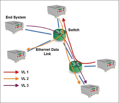
 ARINC 664 defines the use of IEEE 802.3 Ethernet and Internet Protocols (IP, UDP, SNMP, …) for avionics applications. AFDX is a specific, deterministic implementation of an ARINC 664 network which has been developed by Airbus for the A380, A350, and A400M aircraft programs. Other ARINC 664, deterministic implementations are used on the Boeing 787, COMAC ARJ21, and Bombardier CSeries aircraft programs. ARINC 664 uses the concept of a Virtual Link (VL) to define logical channels through a switched Ethernet network from a single transmitter to one or more receiving end systems. The VL is identified in a 16-bit field of the destination Ethernet address of frames. In addition to providing a logical path through the network, VLs also provide the mechanisms to allow the Ethernet network to be considered deterministic. Each VL is characterized by a Bandwidth Allocation Gap (BAG) and a maximum allowed Ethernet frame size.
The BAG defines the minimum time distance between two consecutive frames on the VL and the transmitter is required to adhere to this “speed limit”. The network switches have the responsibility to monitor and “police” the VLs to ensure that the transmitters are not violating the BAG.
As a result, the VL concept allows system designers to a partition and prioritize the resources of the shared Ethernet network to provide a guaranteed minimum level of service. Upper layer protocols such as Internet Protocol (IP) and User Datagram Protocol (UDP) are used on top of Ethernet in ARINC 664 systems. ARINC 664 test instruments must provide support for these protocols as well as the VL traffic shaping feature required at end system devices. In scenarios where a single end node is the UUT, the ARINC 664 test instrument must provide the ability to simulate multiple transmitting (and receiving) end nodes.
Ethernet frames
Therefore, the test instrument must have the capability to send Ethernet frames with multiple Ethernet source addresses. This is something that is not typically possible with a standard Ethernet LAN interface found in a desktop PC. As relatively new protocol, ARINC 664 is often integrated with ARINC 429 within aircraft systems.
Therefore, test instrumentation systems typically require both ARINC 429 and ARINC 664 interfaces and in most cases there are requirements for synchronization of data from both avionics communications interfaces. Again, this makes PXI a logical form factor choice for an ARINC 664 test instrument. The AIT ARINC 664 PXI Test and Simulation module provides a reference design for a flexible and capable ARINC 664 test instrument.
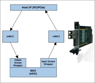
The module uses small form-factor pluggable (SFP) receptacles which allows interchangeable use of either copper or optical Ethernet interface transceivers. Two Ethernet interfaces are provided in a single 3U PXI slot to allow a simultaneous and synchronized access to both sides of a redundant ARINC 664 network.
Parallel processors
At the core of the ARINC 664 test instrument is an FPGA that hosts a custom ARINC 664 specific Media Access Control (MAC) layer capable of doing ARINC 664 output traffic shaping for up to 128 output VLs and ARINC 664 input redundancy management for up to 512 input VLs. The core FPGA also provides two parallel processors which independently host embedded input and output software which handles upper layer protocols such as IP and UDP.
This provides an ultra high performance solution that can support high data rates with minimal host processor loading. The high performance afforded by the on-board upper layer protocol processing and the custom embedded MAC layer allows the test instrument to be used to simulate multiple ARINC 664 end system devices in a single 3U PXI slot.
Legacy avionics
There are several common test and simulation requirements associated with both legacy avionics data bus technologies such as MIL-STD-1553 and ARINC 429 and new emerging avionics network technologies such as ARINC 664/AFDX. These features include:
- the ability to capture bus traffic with synchronized time-stamps for comparison to external events
- the ability to simulate multiple nodes within a single test rack slot
- flexible, reconfigurable bus and network connections and coupling
- high system throughput and channel density
Considering the multiple synchronization facilities, such as PXI triggers – 10MHZ system clock, and PXI STAR trigger – that are provided by PXI along with the use of the PCI and high speed PCI Express system interfaces, it easy to see that PXI is the logical choice for both legacy and emerging avionics test and simulation systems.


