Automotive electronics manufacturers are facing significant challenges with respect to the thermo-mechanical reliability requirements of solder joints. First, there is the increasing harshness of the operating environment as electronic control modules are placed closer to the point of use. Added to this is there is the drive towards miniaturisation to reduce weight along with a demand for an increase in life expectancy as dictated by the warranty periods that car manufactures demand.
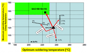
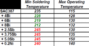
Figure 1 – Plotting the effect of single element additions
A major feature of the harsh environment faced by under hood (power train/chassis) vehicle electronics is that the majority of operation time is conducted at elevated temperatures often with a high level of vibration. Standard SAC based lead-free alloys have offered higher melting points and increased peak-operating temperatures compared to the previously used tin-lead alloys, but still exhibit insufficient creep resistance to meet the most arduous requirements.
Solder alloys in automotive
There are a multitude of process considerations in selecting a lead-free alloy for any electronics manufacturer. Consumer electronics has developed a great deal of knowledge and expertise through their mandated move to lead-free production. This was supported by rapid developments in materials technology as well as the necessary design improvements to production equipment. The vast majority of solder material development driven by that sector focused largely on process performance improvement as well as offering economic advantages.
These developments were driven by the typically high volume, low cost products which were initially covered by the EU RoHS legislation. During this development and evolution of what are now considered mainstream lead-free alloys it was identified that automotive electronics operating temperatures were increasing, and the need for high reliability in the harsh environment of the vehicle engine bay was not going to be delivered by the ‘standard’ tin-silver-copper (SAC) alloys.
A working group consisting of several companies and academic partners was set up in Germany to develop an alloy which was (i) lead-free, (ii) economically viable for mass production and (iii) capable of providing reliable interconnection performance at high temperatures whilst under vibration, exceeding the accepted performance of the benchmark SAC alloys. Alloy requirements The development of any alloy for the high volume automotive electronics industry needed to have several constraints applied if it was to have any chance of being used in production in the future.
The resultant alloy needs to be : (i) Lead-Free: Although at the time of development it was not mandated that all vehicle electronics should be lead-free, it was considered essential to exclude lead from this alloy as future legislation would most likely preclude its use. (ii) An operating Temperature of 150°C: This requirement alone excludes the eutectic tin-lead alloy, but also excludes standard tin-silver, tin-copper and tin-silver–copper alloys. (iii) Survive 1000 thermal cycles of -55°C to +150°C on a wide range of components with no failures. (iv) Acceptable in both cost and relative toxicity: The alloy must have a cost within the same ballpark as the ternary eutectic tin-silver-copper system. Its toxicity must also be deemed acceptable and within the bounds of any current or potential future legislation. The alloy development would work from a baseline, and the following systems were considered: • tin/silver/copper (SAC): Has been shown to offer the best in process yields and is trusted by many users to provide good reliability for many applications. This alloy system has a typically 3-4% Silver content, with the eutectic calculated at 3.8% silver and 0.7% copper. • tin/copper eutectic alloys: While offering a lower raw material cost than SAC alloys, the basic Tin-Copper alloys have been consistently shown to have inferior yield to the SAC alloys, along with reduced reliability. Numerous studies have shown that the Ag3Sn intermetallic needles in the silver bearing alloys give a considerable strength advantage to the alloy, especially when thermally cycled.
Candidate alloying elements
The development of the alloy is done in several stages, the first evaluation criteria is to understand the limitations of the incumbent alloy and of the potential base formulation. At the time of development the majority of existing production was with the tin-lead and tin-lead-silver alloys, which clearly fail on the two foundation requirements of being lead-free and meeting an operating temperature of 150°C. The tin-silver-copper alloy was calculated to have a maximum reliable operating temperature of 120°C using the Coffin/Manson model and calculating from the expected cycles to failure for a tin-lead alloy operating at a peak of 85°C (which is widely regarded as a safe maximum operating temperature).
The challenge then was to look to ways to take the acceptable performance of the SAC alloy in PCB assembly, and modify it within the boundaries set, whilst not compromising the original alloys ‘in-process’ performance. The main target was to increase the creep resistance of the alloy, which would limit early life solder joint failures when operating at elevated temperatures. The known methodology to achieve this was through solid solution strengthening and through dispersion strengthening or hardening of the alloy. The following elements were considered as additions to the tin-silver-copper matrix: • indium (In): Can lower the liquidus of the alloy however cost considerations ruled it out at an early stage. • nickel (Ni): Provides dispersion hardening by means of Intermetallic phase formation. • bismuth (Bi): Provides solid solution hardening AND lowers the liquidus point of the tin based system. • antimony (Sb): Provides solid solution hardening BUT increases the liquidus point of the tin based system.
Development and optimisation
The additional alloying elements where now identified so alloy development and optimisation could begin. A test matrix was established to evaluate the impact of various levels of single element additions of Bismuth (Bi), Antimony (Sb) and Nickel (Ni) on the SAC387 system (Sn-Ag3.8-Cu0.7). This was plotted to chart the effect of each addition on (i) the minimum soldering temperature and (ii) the maximum operating temperature based on the SnPb @ 85°C model. In Figure 1, the green quadrant represents both the target soldering and operational temperature requirements for the development alloy. The effects for various singular element additions are shown in Table 1. It is clear that the “target quadrant” from Figure 1 was unachievable with any single addition. All additions increased the alloy maximum safe operating temperature, with the strongest effect coming from the Antimony additions. Both Antimony and Nickel had the undesired effect of raising the alloy liquidus temperature and as a result a higher minimum soldering temperature would be required. To counter this, Bismuth addition into Tin based solders has an effect to decrease the solidus temperature of the alloy which means that wetting can begin earlier. This solidus lowering effect by Bismuth has been used in other alloy developments, such as for wave soldering low cost temperature sensitive FR-2 laminates for consumer electronics. Development of what would now be a six part alloy continued by combining and optimising the levels of the three dopant elements. The final alloy composition arrived at was SAC387 with 3.0%Bi, 1.4%Sb and 0.15%Ni. This combination delivered on the predicted safe operating temperature of ≥150°C along with a potential minimum soldering temperature of 225°C. This alloy was named “InnoLot”.
Creep performance
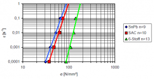
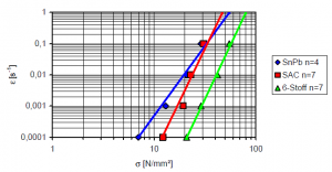
Having designed the alloy how did it perform?. Figures 2 and 3 illustrate the creep rate of the alloys at ambient temperature and at the target maximum use temperature of 150 °C. There is a demonstrable increase in the creep strength with the Innolot alloy which would then be assessed for its effect on the reliability of solder joints during the thermal cycling and vibration test phases of the project. In more recent studies undertaken by the University of Oxford Materials department using alternative indentation based methods to study creep in these alloys (5) similar measurements have been obtained.
Wetting behaviour
In addition to the alloys thermo-mechanical requirements it was always clear that the alloy must provide for a high volume, high yield assembly processes.
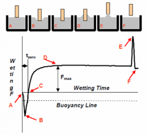
One of the key performance indicators for this was the wetting behaviour of the alloy compared to the baseline SAC387. Adding alloying elements that improve the thermo-mechanical performance but decrease the process ability (wetting) of the alloy would have been a retrograde step. A wetting study was undertaken which included variations in soldering atmosphere; solder alloy temperature and surface finish. Wetting Balance Tests have been generally used to measure the solderability of components and as an aid to developing and testing fluxes. However if all other test variables are kept constant and then only the alloy changed then this can be used as a relative measure of the alloy’s influence on performance. Wetting tests were carried out on a wetting balance tester using 2 atmospheres (air and nitrogen), with three solder temperatures (225, 235 and 260°C).Measurements were taken from each trace which were maximum wetting force (F max) and Time to zero wetting force (T zero). F max is shown by position “D” on the following diagram, and T zero is shown as point “C”. The key requirement for the alloy development was to perform as well as the standard SAC alloy. Wetting evaluation focused on several component and PCB finishes, and one of the key indicators was determined to be performance on OSP Copper which would be tested as received and after thermal ageing.
The results for the Copper OSP surface (as received) are shown in Figure 5. Note that the development InnoLot alloy shows faster wetting speed than SAC387 at the lower solder temperature, but equal speeds at higher temperatures. It is believed that this performance difference is facilitated by the Bismuth inclusion in the alloy.
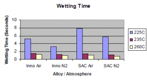
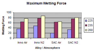
In Figures 7 and 8 we show the wetting time and wetting force respectively.At the lower test temperature of 225 °C the InnoLot shows a clear improvement in wetting force and time when compared to the baseline. At temperatures of 235 °C and above there is comparable performance.This is indicative that the alloy could meet a reduction in process temperature when compared to the SAC387 alloy.
Reliability testing
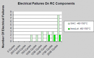
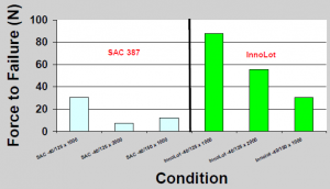
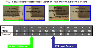
After confirmation that the properties and soldering performance of the alloy had met their design criteria, the next phase was to start the mechanical reliability testing. This compared the InnoLot alloy to its baseline, SAC387. Initial thermal cycling was carried out and rigid devices from RC0402’s to RC2512s were electrically monitored and the number of failures plotted every 250 cycles up to 2000 cycles. This is shown in Figure 7. SAC387 showed significant failures after 750 cycles whereas Innolot did not show any until after 1500 cycles. The next phase was high speed shear strength testing after various thermal cycling regimes. This showed that the Innolot alloy had equivalent results after a -40/+150 1000 cycle regime as SAC387 after a -40/+125 100 cycle regime. Beyond 1000 cycles with the -40/+125 °C test the performance gap between the alloys widens considerably. The final phase of reliability screening was to thermally cycle the test boards and add the vibration component. At this phase of testing the SAC387 alloy really does perform poorly. Vibration without thermal cycles on SAC387 starts to show cracks at the alloy PCB interface on rigid devices. There is no evidence with the InnoLot alloy. Once a thermal cycling component is added to the vibration SAC387 suffers from gross failures while InnoLot alloy remains intact.
Volume production
The development of the InnoLot alloy by a consortium of end users, suppliers and academia has provided a solution for electronics assemblies which are subject to continual vibration and high temperatures where conventional SAC lead-free alloys have not been robust enough.
Since its inception in 2004 this material has been adopted by a number of automotive assemblers and has therefore moved from the laboratory into volume production use. InnoLot continues to gather interest by other automotive electronics assemblers not currently using it as they come across reliability problems when their standard SAC alloys fail to meet new and more harsh environmental tests. The vast majority of use to date has focused on the SMT reflow process however it is use in some selective soldering applications.

